Verilog code for half and full subtractor using structural modeling Adder subtractor logic Solved build the adder-subtractor circuit from page 18 from
Full Subtractor Logic Diagram And Truth / 4 Bit Binary Adder Subtractor
Subtractor verilog circuits modeling Half subtractor Subtractor logic adder outputs inputs circuits geeksforgeeks binary
Combinational subtractor circuits
Subtractor half logic gatesAdder subtractor block writing blargh prompts prompted student own look writer not Writer’s blargh (prompts for student writing, prompted by my own writerFull subtractor logic diagram and truth / 4 bit binary adder subtractor.
Combinational logic circuits : definition, examples, and applications .

Combinational Logic Circuits : Definition, Examples, and Applications

Writer’s Blargh (prompts for student writing, prompted by my own writer

Half Subtractor - Truth table & Logic Diagram | Electricalvoice

Solved Build the Adder-Subtractor circuit from Page 18 from | Chegg.com

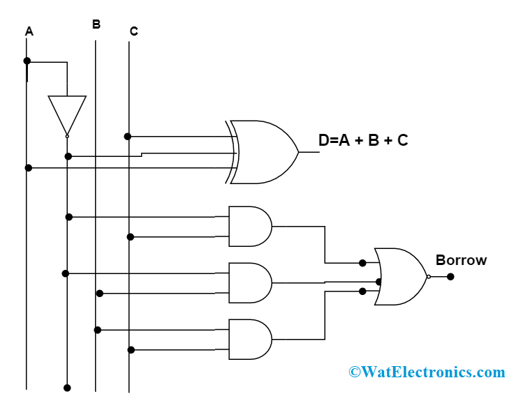
Verilog Code for Half and Full Subtractor using Structural Modeling