Learn how to interpret interlocking schemes between mv cubicles (single Permissive and interlock circuits Interlock module chamber arrangement
PLC Connection : Instrument, Junction Box, Marshalling & System Cabinet
Interlocking electrical control power diagram system diagrams Dortronics_simple-interlock-graph Schematic diagram of interlock of bems.
Interlock system logic diagram burner management sequence starting fuel instrumentationtools rare moon middle case another very which blue
Interlock bemsInterlock diagram. it uses two units to protect the module inside the Plc connection : instrument, junction box, marshalling & system cabinetPermissive interlock circuits logic schematic hatches circled diagonal schematics energize condition.
Interlock turbine instrumentationWiring mv line single electrical mastering diagrams cubicles interlocking between switchgear Interlock door doors graph simple systems practices selecting installing technology access twoDiagrams instrumentation.

Turbine trip interlock system
Interlock permissive contacts auxiliary ladder interlocking circuits energized normallyInstrumentation loop diagrams Diagram instrumentation plc system flow dcs control connection basic architecture marshalling cabinet instrument box junction animation controller wiring block systemsBurner management system logic and interlock.
Reddy heater wiring diagram – easy wiringInstrument loop diagram basics Wiring interlock interlocking wiringg device doorsPermissive and interlock circuits.

List of instrumentation project engineering documents
What is electrical interlocking?Wiring heater reddy interlock failsafe Electric motor wiring diagram forward reverseLoop instrument instrumentation basics.
.


Learn how to interpret interlocking schemes between MV cubicles (single

Burner Management System Logic and Interlock - InstrumentationTools

Permissive and Interlock Circuits | Ladder Logic | Electronics Textbook

Reddy Heater Wiring Diagram – Easy Wiring

Schematic diagram of interlock of BEMS. | Download Scientific Diagram

Dortronics_Simple-Interlock-Graph - Construction Specifier

PLC Connection : Instrument, Junction Box, Marshalling & System Cabinet
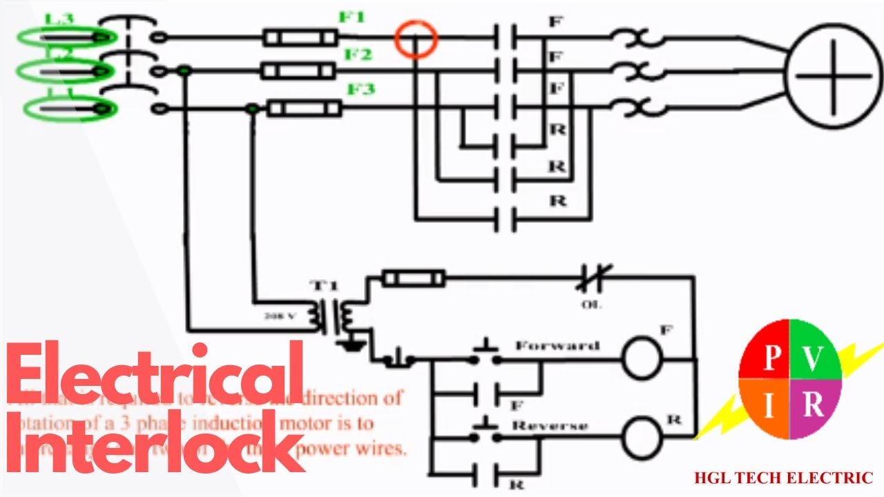
Electric Motor Wiring Diagram Forward Reverse - Collection

Turbine trip interlock System | Instrumentation